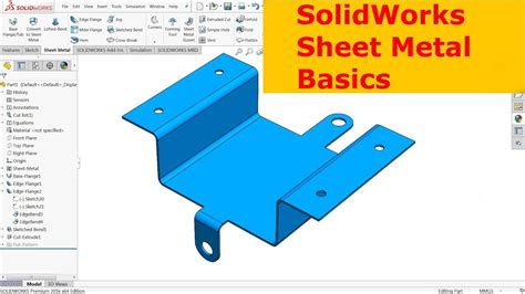
create sheet metal part solidworks Sheet Metal teaches you how to build sheet metal parts using SOLIDWORKS . $49.99
0 · sheet metal drawing in SolidWorks
1 · sheet metal 3d sketch SolidWorks
2 · SolidWorks sheet metal template
3 · SolidWorks sheet metal pdf
4 · SolidWorks sheet metal part drawing
5 · SolidWorks sheet metal drawing pdf
6 · SolidWorks sheet metal download
7 · SolidWorks sheet metal basics
Weather Guard 72 in. x 20.5 in. White Steel Full Size Deep Crossbed Truck Tool Box
You can design a sheet metal part on its own without any references to the parts it will enclose, you can design the part in the context of an assembly that contains the enclosed components, or you can design the part within another part document in a multibody environment.

alloy material cnc casting machining parts supplier
The Convert to Sheet Metal command lets you specify the thickness, bends, and .In this blog you’ll learn how to use the Convert to Sheet Metal tool to build .Sheet Metal teaches you how to build sheet metal parts using SOLIDWORKS .

sheet metal drawing in SolidWorks
The Convert to Sheet Metal command lets you specify the thickness, bends, and .The Convert to Sheet Metal command lets you specify the thickness, bends, and rips necessary to convert a solid part to a sheet metal part. Create the solid part. Click Convert to Sheet Metal .
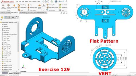
In this lesson, you create the sheet metal part. This lesson demonstrates: 1.Creating a base flange 2.Adding a miter flange 3.Mirroring the part and creating. SOLIDWORKS 3D allows you to quickly create sheet metal part designs using a simple design process, saving you time and development costs, thanks to specific sheet metal features. We can use these features to create . Step 1: Open SolidWorks New Part File. Open SolidWorks and create new Part file. Then select any default plane (e.g. Top plane) and apply “Normal To” view. Step 2: Insert Base Flange Sheet Metal to Part File. Go to . In this blog you’ll learn how to use the Convert to Sheet Metal tool to build sheet metal assemblies with multiple sheets the easy way.
sheet metal 3d sketch SolidWorks
SolidWorks sheet metal template
Sheet Metal teaches you how to build sheet metal parts using SOLIDWORKS mechanical design automation software. Building standalone sheet metal parts, and converting conventional parts to sheet metal, including in assembly .

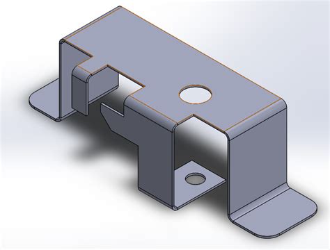
Sheet metal parts are made with a constant thickness. They start out as one flat sheet and then are cut and bent to make the final product. When it comes to creating a sheet metal part in SOLIDWORKS you have two choices .
The Convert to Sheet Metal command lets you specify the thickness, bends, and rips necessary to convert a solid part to a sheet metal part. Create the solid part. Click Convert to Sheet Metal .
You can design a sheet metal part on its own without any references to the parts it will enclose, you can design the part in the context of an assembly that contains the enclosed components, or you can design the part within another part document in a multibody environment.The Convert to Sheet Metal command lets you specify the thickness, bends, and rips necessary to convert a solid part to a sheet metal part. Create the solid part. Click Convert to Sheet Metal (Sheet Metal toolbar) or Insert > Sheet Metal > Convert To Sheet Metal . Select Use gauge table. There are multiple methods for making sheet metal parts in Solidworks using the Sheet Metal tab. In this article, we will look at using the Sketched Bend feature and also the Edge Flange feature. Both of these features are used to create bends starting from a flat piece of metal.In this lesson, you create the sheet metal part. This lesson demonstrates: 1.Creating a base flange 2.Adding a miter flange 3.Mirroring the part and creating.
SOLIDWORKS 3D allows you to quickly create sheet metal part designs using a simple design process, saving you time and development costs, thanks to specific sheet metal features. We can use these features to create sheet metal designs with several different methods. Step 1: Open SolidWorks New Part File. Open SolidWorks and create new Part file. Then select any default plane (e.g. Top plane) and apply “Normal To” view. Step 2: Insert Base Flange Sheet Metal to Part File. Go to “Insert” menu, select “Sheet Metal” from drop down menu and select “Base Flange” from side drop down menu.
In this blog you’ll learn how to use the Convert to Sheet Metal tool to build sheet metal assemblies with multiple sheets the easy way.Sheet Metal teaches you how to build sheet metal parts using SOLIDWORKS mechanical design automation software. Building standalone sheet metal parts, and converting conventional parts to sheet metal, including in assembly context, are covered.
Sheet metal parts are made with a constant thickness. They start out as one flat sheet and then are cut and bent to make the final product. When it comes to creating a sheet metal part in SOLIDWORKS you have two choices for the first step: converting to sheet metal or building up from a base.The Convert to Sheet Metal command lets you specify the thickness, bends, and rips necessary to convert a solid part to a sheet metal part. Create the solid part. Click Convert to Sheet Metal (Sheet Metal toolbar) or Insert > Sheet Metal > Convert To Sheet Metal . Select Use gauge table.You can design a sheet metal part on its own without any references to the parts it will enclose, you can design the part in the context of an assembly that contains the enclosed components, or you can design the part within another part document in a multibody environment.
The Convert to Sheet Metal command lets you specify the thickness, bends, and rips necessary to convert a solid part to a sheet metal part. Create the solid part. Click Convert to Sheet Metal (Sheet Metal toolbar) or Insert > Sheet Metal > Convert To Sheet Metal . Select Use gauge table.
SolidWorks sheet metal pdf
There are multiple methods for making sheet metal parts in Solidworks using the Sheet Metal tab. In this article, we will look at using the Sketched Bend feature and also the Edge Flange feature. Both of these features are used to create bends starting from a flat piece of metal.In this lesson, you create the sheet metal part. This lesson demonstrates: 1.Creating a base flange 2.Adding a miter flange 3.Mirroring the part and creating. SOLIDWORKS 3D allows you to quickly create sheet metal part designs using a simple design process, saving you time and development costs, thanks to specific sheet metal features. We can use these features to create sheet metal designs with several different methods. Step 1: Open SolidWorks New Part File. Open SolidWorks and create new Part file. Then select any default plane (e.g. Top plane) and apply “Normal To” view. Step 2: Insert Base Flange Sheet Metal to Part File. Go to “Insert” menu, select “Sheet Metal” from drop down menu and select “Base Flange” from side drop down menu.
In this blog you’ll learn how to use the Convert to Sheet Metal tool to build sheet metal assemblies with multiple sheets the easy way.
Sheet Metal teaches you how to build sheet metal parts using SOLIDWORKS mechanical design automation software. Building standalone sheet metal parts, and converting conventional parts to sheet metal, including in assembly context, are covered. Sheet metal parts are made with a constant thickness. They start out as one flat sheet and then are cut and bent to make the final product. When it comes to creating a sheet metal part in SOLIDWORKS you have two choices for the first step: converting to sheet metal or building up from a base.
SolidWorks sheet metal part drawing
Get free shipping on qualified Weatherproof Covers products or Buy Online Pick Up in Store today in the Electrical Department.
create sheet metal part solidworks|sheet metal 3d sketch SolidWorks