bonding jumper electrical box To bond one end of the service raceway to the service neutral conductor, you must use a listed bonding wedge or bushing with a bonding jumper. Size it per Table 250.66, based on the area of the largest ungrounded .
The J24 is a large junction box complete with lid tamper detection. It provides 24 terminals for wiring, with two reserved for tamper functionality.
0 · supply side bonding jumper diagram
1 · main bonding jumper vs system
2 · main bonding jumper in panel
3 · main bonding jumper diagram
4 · bonding jumpers should be sized
5 · bonding jumpers must be insulated
6 · bonding jumper wire size chart
7 · bonding jumper size chart
Keep those manifolds sparkling clean with our irrigation valve box collection! Rectangular and round box styles available. Shop now!

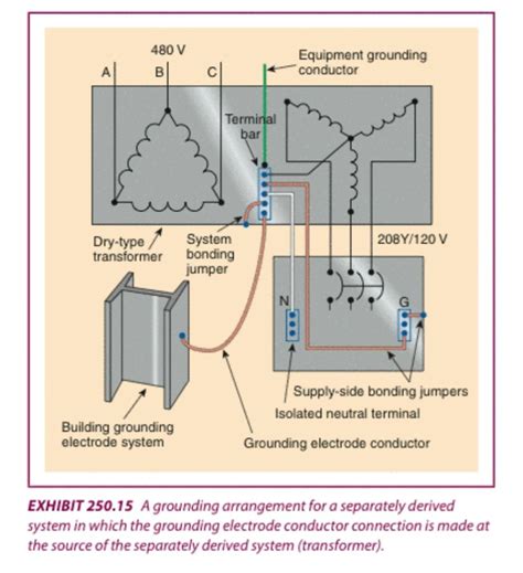
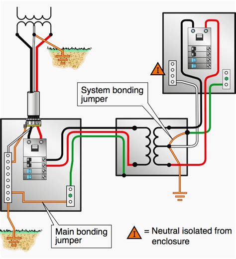
The main bonding jumper connects the service neutral wiring to the grounding electrode conductor(s) (GEC), and also to the service enclosure (panel box). By connecting these three components together, it eliminates any .“Grounding” and “bonding” are important elements of a building’s electrical wiring system. They each have different functions, but they work together to make the building’s electrical wiring safe. For our typical AC electrical system, the purpose of the “Main Bonding Jumper” is to connect the equipment grounding conductors (E.G.C.) contained in each branch-circuit and the metal (conductive) service .When preparing bonding jumpers for expansion joints, leave an extra bend in the wire or use a flexible bonding jumper to keep a good connection even when the tray expands and contracts. .
The main and system bonding jumpers are the critical point in the grounding and bonding system that ensure the safety of those around electrical equipment. Understanding how to size and install them is critical to .

To bond one end of the service raceway to the service neutral conductor, you must use a listed bonding wedge or bushing with a bonding jumper. Size it per Table 250.66, based on the area of the largest ungrounded . It requires a bonding jumper to connect the grounding terminal of a receptacle (green screw) to the metal box; with the metal box then connected to the system EGC. However, the additional subsections point out that meeting .
The green bonding jumper at the top is prefabricated with listed tool-crimp connectors at each end. The red twist-on connector can be used for grounding and bonding applications. The tool-applied crimps (bottom center) . Concentric or eccentric knockouts that are part of a cabinet, cutout box, junction box, or pull box, installed on an electrical system that has a voltage over 250 volts have not been investigated for grounding and bonding, and . The main bonding jumper connects the service neutral wiring to the grounding electrode conductor(s) (GEC), and also to the service enclosure (panel box). By connecting these three components together, it eliminates any voltage potential (current) between them.“Grounding” and “bonding” are important elements of a building’s electrical wiring system. They each have different functions, but they work together to make the building’s electrical wiring safe.
supply side bonding jumper diagram
Equipment bonding jumper is the connection between two or more portions of the equipment grounding conductor. A conductor installed in the raceway between the two boxes in Figure 1 would be classified as an equipment bonding jumper. For our typical AC electrical system, the purpose of the “Main Bonding Jumper” is to connect the equipment grounding conductors (E.G.C.) contained in each branch-circuit and the metal (conductive) service-disconnect enclosure to the Neutral Conductor of the electrical service.When preparing bonding jumpers for expansion joints, leave an extra bend in the wire or use a flexible bonding jumper to keep a good connection even when the tray expands and contracts. Cable tray can expand several inches in either direction during extreme heat or cold conditions.
The main and system bonding jumpers are the critical point in the grounding and bonding system that ensure the safety of those around electrical equipment. Understanding how to size and install them is critical to understanding how to create a safe grounded electrical system meeting Section 250.4. To bond one end of the service raceway to the service neutral conductor, you must use a listed bonding wedge or bushing with a bonding jumper. Size it per Table 250.66, based on the area of the largest ungrounded service conductors within the raceway [250.102 (C)]. It requires a bonding jumper to connect the grounding terminal of a receptacle (green screw) to the metal box; with the metal box then connected to the system EGC. However, the additional subsections point out that meeting certain provisions is not required. The green bonding jumper at the top is prefabricated with listed tool-crimp connectors at each end. The red twist-on connector can be used for grounding and bonding applications. The tool-applied crimps (bottom center) are listed for stranded conductors only.
Concentric or eccentric knockouts that are part of a cabinet, cutout box, junction box, or pull box, installed on an electrical system that has a voltage over 250 volts have not been investigated for grounding and bonding, and would therefore .
The main bonding jumper connects the service neutral wiring to the grounding electrode conductor(s) (GEC), and also to the service enclosure (panel box). By connecting these three components together, it eliminates any voltage potential (current) between them.
“Grounding” and “bonding” are important elements of a building’s electrical wiring system. They each have different functions, but they work together to make the building’s electrical wiring safe. Equipment bonding jumper is the connection between two or more portions of the equipment grounding conductor. A conductor installed in the raceway between the two boxes in Figure 1 would be classified as an equipment bonding jumper.
china cnc aluminium turning machining
For our typical AC electrical system, the purpose of the “Main Bonding Jumper” is to connect the equipment grounding conductors (E.G.C.) contained in each branch-circuit and the metal (conductive) service-disconnect enclosure to the Neutral Conductor of the electrical service.When preparing bonding jumpers for expansion joints, leave an extra bend in the wire or use a flexible bonding jumper to keep a good connection even when the tray expands and contracts. Cable tray can expand several inches in either direction during extreme heat or cold conditions. The main and system bonding jumpers are the critical point in the grounding and bonding system that ensure the safety of those around electrical equipment. Understanding how to size and install them is critical to understanding how to create a safe grounded electrical system meeting Section 250.4.
china cnc aluminum processing parts
To bond one end of the service raceway to the service neutral conductor, you must use a listed bonding wedge or bushing with a bonding jumper. Size it per Table 250.66, based on the area of the largest ungrounded service conductors within the raceway [250.102 (C)]. It requires a bonding jumper to connect the grounding terminal of a receptacle (green screw) to the metal box; with the metal box then connected to the system EGC. However, the additional subsections point out that meeting certain provisions is not required. The green bonding jumper at the top is prefabricated with listed tool-crimp connectors at each end. The red twist-on connector can be used for grounding and bonding applications. The tool-applied crimps (bottom center) are listed for stranded conductors only.
main bonding jumper vs system
main bonding jumper in panel
Inside/Outside Kennels; Kennel & Dog House Combos. Basic K9 Condos ; Complete K9 Condos; Ultimate K9 Condos ; Room Dividers; . Dog House Accessories; Metal Dog Houses; Composite Dog Houses; HDPE & Vinyl Dog Houses; Castle & Barn Dog Houses; . Mossy Oak Rustic Lodge Medium Dog House . Special Price $89.00 Regular Price $231.00. Out of stock .
bonding jumper electrical box|main bonding jumper diagram