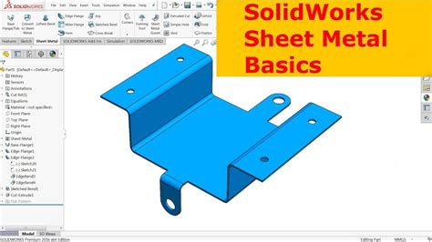
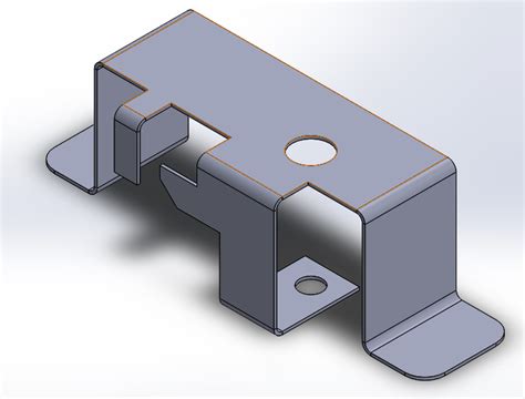
creating sheet metal part in solidworks Create new bodies in an existing sheet metal part using Base Flange, Convert . The HC2A-FS Steelheart Series Upright two section heated cabinet with full stainless doors is a space saving workhorse. Solid state digital controller with temperature alarms and LED display (°F or °C).
0 · sheet metal drawing in SolidWorks
1 · sheet metal 3d sketch SolidWorks
2 · SolidWorks sheet metal template
3 · SolidWorks sheet metal pdf
4 · SolidWorks sheet metal part drawing
5 · SolidWorks sheet metal drawing pdf
6 · SolidWorks sheet metal download
7 · SolidWorks sheet metal basics
Explore a wide range of our Twisted Metal Long Box selection. Find top brands, exclusive offers, and unbeatable prices on eBay. Shop now for fast shipping and easy returns!
The Convert to Sheet Metal command lets you specify the thickness, bends, and rips necessary to convert a solid part to a sheet metal part. Create the solid part. Click Convert to Sheet Metal (Sheet Metal toolbar) or Insert > Sheet Metal > Convert To Sheet Metal . Select Use gauge table.Create new bodies in an existing sheet metal part using Base Flange, Convert .You can create a sheet metal part by converting a solid or surface body using .You can design a sheet metal part on its own without any references to the parts .
Create new bodies in an existing sheet metal part using Base Flange, Convert to Sheet Metal, Insert Bends, and Lofted-Bend commands. Split a single sheet metal part into multiple bodies. . In this lesson, you create the sheet metal part. This lesson demonstrates: 1.Creating a base flange 2.Adding a miter flange 3.Mirroring the part and creating. SOLIDWORKS 3D allows you to quickly create sheet metal part designs using a simple design process, saving you time and development costs, thanks to specific sheet metal features. We can use these features to create .You can create a sheet metal part by converting a solid or surface body using the Convert to Sheet Metal tool. After you create the sheet metal part, you can apply all sheet metal features .

You can design a sheet metal part on its own without any references to the parts it will enclose, you can design the part in the context of an assembly that contains the enclosed components, .To create a sheet metal part with round bends: Sketch a closed or open profile. Create a thin feature part. Depending on the type of profile, you can use tools such as Shell or Extruded . There are multiple methods for making sheet metal parts in Solidworks using the Sheet Metal tab. In this article, we will look at using the Sketched Bend feature and also the Edge Flange feature. Both of these .When you create a drawing of your sheet metal part, a flat pattern is automatically created. Drawings of sheet metal parts can also contain views of the bent sheet metal part. You can .
The Convert to Sheet Metal command lets you specify the thickness, bends, and rips necessary to convert a solid part to a sheet metal part. Create the solid part. Click Convert to Sheet Metal (Sheet Metal toolbar) or Insert > Sheet Metal > Convert To Sheet Metal . Select Use gauge table.Create new bodies in an existing sheet metal part using Base Flange, Convert to Sheet Metal, Insert Bends, and Lofted-Bend commands. Split a single sheet metal part into multiple bodies. Insert one or more sheet metal, weldment, or other bodies into an existing sheet metal part.
In this lesson, you create the sheet metal part. This lesson demonstrates: 1.Creating a base flange 2.Adding a miter flange 3.Mirroring the part and creating. Step 1: Open SolidWorks New Part File. Open SolidWorks and create new Part file. Then select any default plane (e.g. Top plane) and apply “Normal To” view. Step 2: Insert Base Flange Sheet Metal to Part File. Go to “Insert” menu, select “Sheet Metal” from drop down menu and select “Base Flange” from side drop down menu. SOLIDWORKS 3D allows you to quickly create sheet metal part designs using a simple design process, saving you time and development costs, thanks to specific sheet metal features. We can use these features to create sheet metal designs with several different methods.You can create a sheet metal part by converting a solid or surface body using the Convert to Sheet Metal tool. After you create the sheet metal part, you can apply all sheet metal features to it. Use the Convert to Sheet Metal tool with:
You can design a sheet metal part on its own without any references to the parts it will enclose, you can design the part in the context of an assembly that contains the enclosed components, or you can design the part within another part document in a multibody environment.To create a sheet metal part with round bends: Sketch a closed or open profile. Create a thin feature part. Depending on the type of profile, you can use tools such as Shell or Extruded Boss/Base to create thin features. Click Insert Bends (Sheet Metal toolbar) or Insert > . There are multiple methods for making sheet metal parts in Solidworks using the Sheet Metal tab. In this article, we will look at using the Sketched Bend feature and also the Edge Flange feature. Both of these features are used to create bends starting from a flat piece of metal.
When you create a drawing of your sheet metal part, a flat pattern is automatically created. Drawings of sheet metal parts can also contain views of the bent sheet metal part. You can create a configuration in a sheet metal part that shows the flattened part. Sheet metal gauge/bend tables store properties for a designated material.The Convert to Sheet Metal command lets you specify the thickness, bends, and rips necessary to convert a solid part to a sheet metal part. Create the solid part. Click Convert to Sheet Metal (Sheet Metal toolbar) or Insert > Sheet Metal > Convert To Sheet Metal . Select Use gauge table.Create new bodies in an existing sheet metal part using Base Flange, Convert to Sheet Metal, Insert Bends, and Lofted-Bend commands. Split a single sheet metal part into multiple bodies. Insert one or more sheet metal, weldment, or other bodies into an existing sheet metal part.
In this lesson, you create the sheet metal part. This lesson demonstrates: 1.Creating a base flange 2.Adding a miter flange 3.Mirroring the part and creating. Step 1: Open SolidWorks New Part File. Open SolidWorks and create new Part file. Then select any default plane (e.g. Top plane) and apply “Normal To” view. Step 2: Insert Base Flange Sheet Metal to Part File. Go to “Insert” menu, select “Sheet Metal” from drop down menu and select “Base Flange” from side drop down menu. SOLIDWORKS 3D allows you to quickly create sheet metal part designs using a simple design process, saving you time and development costs, thanks to specific sheet metal features. We can use these features to create sheet metal designs with several different methods.You can create a sheet metal part by converting a solid or surface body using the Convert to Sheet Metal tool. After you create the sheet metal part, you can apply all sheet metal features to it. Use the Convert to Sheet Metal tool with:
massachusetts sheet metal license renewal
You can design a sheet metal part on its own without any references to the parts it will enclose, you can design the part in the context of an assembly that contains the enclosed components, or you can design the part within another part document in a multibody environment.To create a sheet metal part with round bends: Sketch a closed or open profile. Create a thin feature part. Depending on the type of profile, you can use tools such as Shell or Extruded Boss/Base to create thin features. Click Insert Bends (Sheet Metal toolbar) or Insert > . There are multiple methods for making sheet metal parts in Solidworks using the Sheet Metal tab. In this article, we will look at using the Sketched Bend feature and also the Edge Flange feature. Both of these features are used to create bends starting from a flat piece of metal.
sheet metal drawing in SolidWorks
sheet metal 3d sketch SolidWorks
SolidWorks sheet metal template

This article describes a very basic BFO detector which uses only two transistors and an LM389 audio amplifier. The LM389, in fact, contains the two transistors that form the search and reference oscillators so the whole circuit is comprised of a single IC and a handful of discrete linear components.
creating sheet metal part in solidworks|SolidWorks sheet metal pdf