inventor unfold sheet metal Define Sheet Metal Unfold Rules Using Linear Approximation. This method unfolds sheet metal part using a KFactor that is applied uniformly to all bend angles. For Unfold Method, select fx . Welding primarily focuses on joining metal parts together, while metal fabrication involves multiple processes to shape and assemble metal structures. In simpler terms, welding is a part of the broader metal fabrication process.Based out of San Antonio, Texas we are a select group of metal fabricators; painters; lighting-assembly specialists and more. With a flare for elegant production solutions, we bring our customers creative business designs to reality.
0 · inventor sheet metal thickness
1 · inventor sheet metal fold
2 · inventor sheet metal drawing
3 · inventor sheet metal defaults
4 · inventor sheet metal bend
5 · inventor convert to sheet metal
6 · inventor change sheet metal thickness
7 · autodesk inventor sheet metal tutorial
Willoughby Roofing & Sheet Metal, Inc. is a licensed, bonded, and insured General Contractor working in the commercial and industrial roofing sector with over 70 years of experience. Our areas of focus include: government, industrial, automotive, retail, schools, and healthcare facilities. WRSM, Inc. installs all types of roofing systems .
You can unfold and refold the following sheet metal features: Sheet metal bends or rolls relative to a reference face. You can unfold a model that has at least one flat face. You can refold sheet metal models that have at least one unfold .

Stuart Smith, Manufacturing Consultant at Adris Professional Services takes you through the 'unfold and refold' feature for sheet metal in this installment o.Open the new part file to unfold the part. On the ribbon, click Sheet Metal tab Modify panel Unfold . Do one of the following: For sheet metal bends or rolls relative to a face, click a face or plane .
I received a step file of a sheet metal part but I don't know what I need to do to the model to flatten/unfold it. (I'm using Inventor 2018 professional) Solved!
Define Sheet Metal Unfold Rules Using Linear Approximation. This method unfolds sheet metal part using a KFactor that is applied uniformly to all bend angles. For Unfold Method, select fx . Inventor Sheet Metal Unfold and Refold. ARKANCE UK. 4.83K subscribers. Subscribed. 6. 2.8K views 4 years ago #Cadline. Taken from #Cadline Community blogs For more videos, visit Cadline. In this comprehensive tutorial, you'll dive into the essential sheet metal design techniques in Autodesk Inventor. Learn how to use the Contour Roll, Unfold,.
See our overview video below which explains the sheet metal unfold, refold function in Inventor in a little more detail!Unfold adds an unfold feature to your sheet metal part browser. You can add other features to the flattened portion of the model. A refold feature can then be added to refold all or some of the . 578 views 3 years ago AutoDesk INVENTOR Sheet Metal. AUTODESK INVENTOR Basic Training Tutorial (Full Course 7hr:55min) playList • AUTODESK INVENTOR .
Hi! The rectangular flat pattern is a representation of an unrolled elbow. The rolled (Contour Roll) shape created in Inventor Sheet Metal is meant for keeping the unfold length of linear extensions on both ends intact. The roll . Inventor Forum > how to unfold a tapered tube and flatten it out using sheet metal; Inventor. Community Forums; Inventor Forum Welcome to Autodesk’s Inventor Forums. Share your knowledge, ask questions, and . Doing that will keep consistent thickness and then the part will work just fine in Inventor (don't forget to set the sheet metal style in Inventor to the right thickness too before trying to unfold Inventor 2023 - Dell Precision 5570 I wanted to convert this to a sheet metal part and then unfold it so I could see what the flat pattern looked like. However, when I attempt to use the "Unfold" command it fails. Similarly, the Flat Pattern command fails as well. . In your example Inventor incorrectly mapped the points for the Loft. Sometimes it does this. (usually when the .
Select all Unfold features/actions in model browser under 'Folded Model' and suppress. Edit model. Inventor requires at least one surface that connects all the bends in a continuity way for surface that has not been interrupted (cannot appear point/position G0).If this condition is met, flat pattern will be crated for bends which meet rest of the sheet metal rules. All the parts we process are sheet metal parts but if a designer forgot to create the flat pattern the batch routine will try and create it. We have noticed that this auto unfolding routine has become more unreliable than in the past version of Inventor. We use the standard API function "oSheetCompDef.Unfold()" to create the flat pattern .
inventor sheet metal thickness
So sorry. I have created a contour rolled part in Inventor Sheet Metal. I have used the Unfold command which shows a nice view of the profile that I used to create the part. I know I can do a section view in the folded state and practically get the same view but I am just curious if I can make an 'unfolded' view and a 'folded' view of the part .Define Sheet Metal Unfold Rules Using Linear Approximation. This method unfolds sheet metal part using a KFactor that is applied uniformly to all bend angles. For Unfold Method, select fx Linear. Enter a new KFactor value if needed. Adjust the Spline Factor value if needed (the default is 0.5). This value affects the flattened sizes of contour . Inventor can only create a flat pattern by unwrapping in one axial direction at a time. Inventor has limited ability to unfold spline faces; If the part is twisted or is bent in more than one axial direction at a time the Inventor flat pattern will fail. Inventor sheet metal is not yet able to unfold and refold or flatten nonlinear bends. Unable to unfold and create flat pattern of sheet metal part. How to review a sheet metal part that will not unfold. The nonuniformed thickness of the model represents sheet metal thickness. To flatten a sheet metal part it must have a uniform thickness. Using an incorrect sheet metal rule. Check to see the sheet metal rule and the model match. Using nonsheet metal .
steel box dimensions
My company has set up a LOT of Sheet Metal Defaults. In every instance, when we start a new sheet metal part or edit an existing one, we click on the "Sheet Metal Defaults" button on the Ribbon. This popup appears: The Material shows TFC SH CS (this is correct for this Rule). If I click the down arrow next to the Material (TFC SH CS) and scroll to the top of that list, I can . I have a sheet metal part that will be folded manually and not as a brake operation. I want to show it folded in the assembly, but flat for the part drawing and DXF. My initial thought was to create a model state with an unfold feature to use for fab. My DXFS and PDFs of the flat patterns are created automatically, and even though the part has been unfolded, it still shows .
Starting a New Sheet metal File 1. To start a new sheet metal file, click Get Started Launch > New on the ribbon. 2. On the Create New File dialog, click the Sheet Metal.ipt icon, and then click Create. Setting the Parameters of the Sheet Metal part 1. To set the parameters, click Sheet Metal > Setup > Sheet Metal Defaults on the ribbon; the Sheet
steel box containers austin
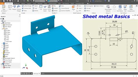
inventor sheet metal fold
I have a part that I created as a standard IPT. I then converted it to sheet metal. I successfully unfolded the converted part into a flat face in the 3D file. When I go to put it into a drawing, I need to have both the flattened part and the bent part. However, when I go to place a "Base" in the drawing file, I only have the option to place a Folded Model. The company I work for has a large number of Left Hand and Right Hand sheet metal parts. To reduce the amount of time needed to create both Left Hand and Right Hand sheet metal parts, I use the Derived Part icon. I create a Left Hand part, use the derive icon with mirroring on and create the Right Hand part. While the Right Hand sheet metal part gets . I hope this clarifies how a bend table can provide a custom deduction value for each thickness, angle, and bend radius, fully customizing the sheet metal unfold style inside of Inventor. For the scenario you are inquiring .

The sheet metal flat pattern is showing wrong side up in the Inventor drawing. The A-Side specifies the up direction of the part. A selected face unfolds the part using the selected face as the base face. Before the flat pattern is created, define the .
A fold on a sheet metal face forms about a straight sketched bend line that terminates at face edges. Unlike the bend, flange, contour flange, or hem features, which all add material to the design, the fold feature does not add material. On the ribbon, click Sheet Metal tab Create panel Fold. Click the bend line to use for the fold. Hi Again ! I have this hopper as derived part which is 100x100x100 cube with loft at bottom. I created sheet metal folding on 1 side and duplicated 4 on assembly. Is it possible to join them up and make into 1 part? Modelling wise, it might be done which i like to know but to achieve in real manufacturing can you fold it 3 90deg and weld in last section or the way is done it is . Inventor Forum > Can't unfold sheet metal for mould; Inventor. Community Forums; Inventor Forum . If you want to create a flat Pattern, you will have more success if you use sheet metal tools. The solid Loft will produce in this case a curved sheet. Regards. CCarreiras Skin.ipt. Report. 1 Like Reply. Message 4 of 20
Hi, Im building a series of flat patterns to create a curved, rectangular section chassis rail. I have created a solid body as a "core" then offset each side by the thickness of the steel, and derived a sheetmetal part from each of the 4 sides. Ive then converted each part to a flat pattern, and exported to .dxf, ready to be sent to a profile cutter.My problem is the inner .
You unfold sheet metal features relative to a plane at the end of the material, or unfold bends or rolls relative to a face. Important: The unfold command requires a single body in a part file. If the part file contains multiple solid bodies, use Make Components or Make Part to export the bodies to a unique part file. Open the new part file to . Sheet Metal Unfold Refold Not the same As you can see in the mp4 movie the after "refold" the part, the geometry is not in the same place as before the "unfold". . This happens when there is no clear reference to start the unfold/refold. Inventor has to supply a "reference" plane. Probably due to some change in geometry after Unfold, the .
When making a drawing view, it would be nice to only unfold specific bends in the folded part. This would allow dimensioning at multiple stages in the forming process. This could possibly be controlled by turning off bends 1,2,3,etc. n the bend table in the flat pattern. Inventor 2020.2.1 I made a contour flange sheetmetal part. The original contour sketch is tied to the part origin. After some unfolding, cutting, patterning and refold features, the solid body is offset from the part origin. What do I need to .With Inventor, you can also edit the selections and values which are used to define Thickness, Bend, Corner, and Flat Pattern options. Edit Unfold Rule. Provides access to the Sheet Metal Unfold edit panel in the Style and Standard Editor. With Inventor you can edit the selections and values which are used to define: linear unfolding method vs . Hi, I have a sheet metal part from CATIA that can be flattened in a CATIA sheet metal environment. I am trying to do a similar thing in Inventor but somehow could not figure out this. please assist, is it possible to unfold or make a flat pattern from uneven sheet metal components, if yes then how? I am sharing the component file if you need it!
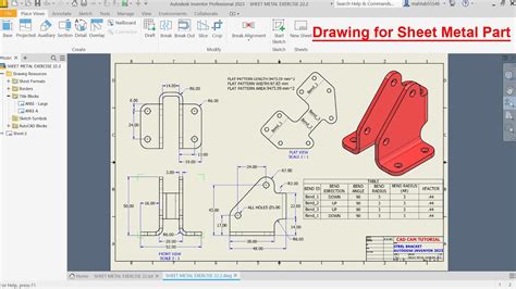
inventor sheet metal drawing

Snap-on Industrial Brand JH Williams 10-Inch metal socket set toolbox is ruggedly constructed for long life and is ideal for storing socket sets, .
inventor unfold sheet metal|inventor sheet metal thickness